SECONDS (SFL Extended CONversational Design System) is an SFL behavior simulator for PARTHENON. SECONDS is an interactive system, which completely controls everything (i.e. reading and simulation of SFL, pattern setup, etc.) by means of commands. SECONDS performs the following:
(1) Commands are read from a "listening-stream" as character strings.
(2) Results of the simulation made by commands are output to a "speaking-stream" as character strings.
(3) Error messages are output to a "claiming-stream" as character strings.
Upon opening the SECONDS, each stream is set as follows:
	listening-stream        : standard input

        speaking-stream	        : standard output

	claiming-stream	        : standard error output
• Simulation procedure
Normally, the following steps are taken to simulate with SECONDS:
(1) Reading SFL (sflreadcommand, sflload command)
(2) Installing simulation images (installcommand, autoinstall command)
(3) Setting simulation patterns (setcommand, sch_add command)
(4) Setting probes (rpt_addcommand)
(5) Executing forward commands
The execution of the above procedure will output the probe value to a speaking-stream as a time series.
• Timing model
Using a "zero-delay delay model," SECONDS simulates synchronous sequential circuits described in SFL.
The clock shown in Fig. 5.1 is assumed, and the values of "objects with memory" (register facilities), such as memory, register, stage, task and segment, are all updated concurrently at each clock pulse.
On the other hand, values of "objects without memory" (terminal facilities), such as control and data terminals, SFL conditional expressions, and inputs of register facilities change instantly upon the change of register facilities. The values of these objects are retained until the next clock pulse. (Phenomena such as hazards cannot be observed.)
The correspondence to real circuits is as follows. The value observed as the result of simulation is shown as 'a.' It represents the value at the time when all the signal values are in a stable state (immediately before the arrival of the next clock pulse). The interval between clock pulses is called the simulation time. Upon the issuance of the first install command (at the time when the simulation image is created), the simulation time is set to 0.
<Fig. 5.1> Timing model of SECONDS

• Conflict resolution
It is assumed in SFL that writing to control a task or control terminals is executed through an OR gate and writing to other facilities through a 3-state gate.
Therefore, if task termination (writing "0") and task creation (writing "1") are carried out for the same task, the task value at the next simulation time is "1." However, if two or more different values are written into other facilities, an error is output. In this case, one of these values is selected based on the SECONDS algorithm, although which value is selected is unpredictable. The simulation can be continued, but the result produced by this simulation may be meaningless.
• 4-value model
The value of each bit in the bit strings that SECONDS handles takes one of the following four values: "0," "1," "u," "z." The meaning of each value is as follows:
	 "0" :logically false

	 "1" :logically true

	 "u" :unknown whether false or true

	 "z" :high impedance (not driven)
High impedance is regarded as equivalent to "u" in every operation. The only time the handling of "u" and "z" differs is when the facility value is reported.
• Operation of "u"
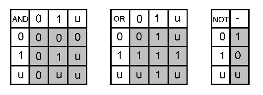
There are many operators in SFL. In general, when "u" is to be operated on, "0" and "1" are applied in turn instead of "u." If the generated bit is the same for both "0" and "1", then it is used as the operation result. If the generated bits differ, "u" is used as the operation result. Table 5-1 shows a truth table of AND, OR and NOT operations.
<Table 5.1> Example of "u" operation
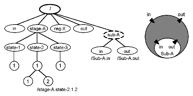
The first step in simulating with SECONDS is to read the applicable SFL description using sflreador sflload command. However, that alone is not enough. These merely collect the parts (module class) that constitute a circuit. To start simulation, the parts must be placed and a circuit must be constructed. In SECONDS, placement of parts is called "instantiation", and the created circuit, a "simulation image." A simulation image is of a tree structure with the first instance created at the root. A module consists of nodes. A tree structure is created underneath the module in accordance with the SFL block structure. Sub-modules are also components of the master module. Furthermore, the SFL conditional or execution statements can be components of the module and appear as nodes in the simulation image.
<Fig. 5.2> Incomplete simulation image and its path names
<Fig.5.3> Incomplete simulation image and its path names
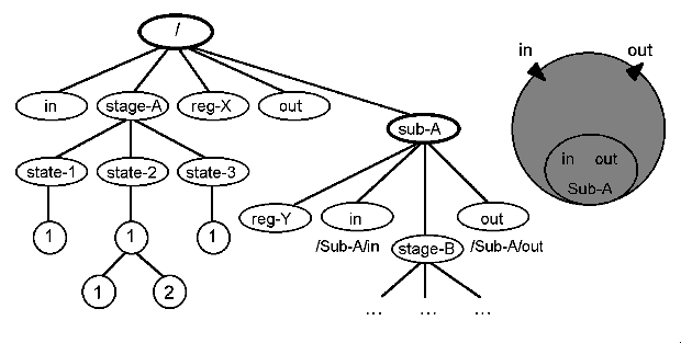
Figure 5.2 illustrates a conceptual diagram of a simulation image just after instantiating a module containing a sub-module named Sub-A as the top module. At this stage, Sub-A has not been instantiated (denoted by a hole), but Sub-A exists as a node (sub-module node). Even without instantiating Sub-A, simulation can proceed (in this case, the input terminals under the sub-module node are treated as equivalent to the output terminals of the top module. Likewise, the output terminals under the sub-module node are treated as equivalent to the input terminals of the top module). Figure 5.3 shows a simulation image after the instantiation of Sub-A.
The simulation image provides the user with a single naming space. A specific node in the simulation image is represented by a series of node names (a path name) on the route from the base node to the specific node. The base node should be either "root"("/"), "present position" (".") or "marker position"("~").
A master node (node closer to the root) is expressed by "a special name ("..")." Although SFL conditional or execution statements do not have names, they are given numbers in the sequence of description within a block in the simulation image so that these numbers can be used as their names.
A delimiter "/" or "." must be inserted between names. However, only the delimiter "/" should follow a module name and a special name such as "." or ".." Putting the delimiter "." after a module name specifies a sub-module node (effective only in a hole-state). The first "./" can be omitted if the base node is the present position.
The move and marker commands can put the present and marker positions to any node in a simulation image (when the simulation image is created, both positions are set to root "/").
Except for modules and sub-modules, any object that is given a name by SFL has a value (stages and segments have states as values and the states have themselves as values). Such a value is called a facility. Upon instantiation of a module, facilities are set as follows based on the type declared by SFL:
	reg	: all bits set to "u"

	reg_wr	: all bits set to "0"

	reg_ws	: all bits set to "1"

	mem	: all bits of all words set to "u"

	stage	: Initial state

	segment	: Initial state of stage

	task	: "0" (inactive)

	Control input terminal	: "0" (not asserted)

	Data input terminal  	: all bits set to "z" (not driven)

	Others	: Calculated by refresh
Facilities (except for state facilities) can be changed using set commands (memset and memclr commands for memory facilities).
The value of a register facility set by these commands is effective until the register is updated. The value of a terminal facility is effective only for the current simulation time.
The hold command can be used to carry the values of the input terminals, etc. beyond the simulation time. The hold command not only prolongs the period in which terminal facilities set by the set command are effective, but also prohibits values from being changed by commands other than the set command. A "hold" state is released by a release command. When a release command is issued to a terminal facility, the value set by the last set command becomes invalid.
Facility values can be displayed by using a print command.
SECONDS receives commands at the point in time shown in Fig 5.1. Therefore, if an install or set command changes the circuit or the values of its components, this will affect the values of terminal facilities, condition values and the values to be loaded into register facilities at the next clock pulse. Re-calculation of these values is called "refreshing."
When a print command is executed, an error message may be generated in some cases but not in others. This is because SECONDS performs the refreshing as follows and only when re-calculation is necessary:
(1) Calculations when values of terminal facility, condition values and registers are updated
(2) Request function
(3) Error report
The request function is to ask the user for the value of a certain terminal facility when it is required in (1) but the terminal facility is not driven. This function is applicable only to data terminals registered by the req_add command. Since this function is not active at the time SECONDS is started, it only becomes usable after it is made active by a request command.
The forward command has a predominant role in SECONDS. It advances simulation time by repeating refreshing operations, administers scheduling and outputs reports.
• Schedule function
This is the function of executing a command string reserved by a sch_add command at a specified simulation time. Simulation patterns can be defined by scheduling set commands.
• Report function
This function displays the value of the facility specified by a rpt_add command in a specified format at each forward command cycle. The function is active when SECONDS is started. It can be cancelled with a report command. When the report function is inactive, report output is skipped.
• Forward command steps
A forward command repeats the following steps until the stop time is encountered. However, if the simulation reaches the time specified by a stop command (stop +1000 is assumed when no time is specified), the forward command ends even before the simulation time specified by the forward command has expired.
(1) Calculation of the stop time
(2) Update of simulation time and registers
(3) Execution of scheduled scripts
(4) Report output
(5) The forward command terminates if the stop time has been reached; otherwise, steps (2) through (5) are repeated.
During steps (2) to (4), refreshing operations are executed as necessary. If the stop time specified by the forward command is the current simulation time, the forward command executes only a refreshing operation. This command may be used to re-display error reports.
Command input (listening-stream) can be switched by listen and eval commands. Switching a listening-stream prompts the execution of command strings (scripts) stored in files or character strings the way a DOS batch file is executed. The n-th parameter in the listen or eval command is set to the n-1-th parameter variable of the script.
Starting SECONDS simply starts the command interpreter with the standard input as a script. Therefore, at the start of SECONDS, the command line parameters are those in the standard input script.
SECONDS supports the concept of variables in order to reduce command inputs, improve script readability and facilitate data exchange between scripts. A parameter variable is either one referred to by a number ($n) or a local or global variable referred to by a name ($name). A local variable is defined with a define command and is effective only within a script. A global variable is defined with a setenv command and is always effective within SECONDS.
When the same name is defined for a local and a global variable, reference by the local variable has priority. The following variables are system-defined in SECONDS. The environmental variables used at the time SECONDS is started are defined as global variables. However, re-definition of variables by a setenv command does not affect the environment of the DOS command executed by an exec command.
	ARGC	: Number of parameters given to a script

	ARGL	: Parameter string given to a script

	POSIT	: Current position in the simulation image

	MARKER	: Marker position in the simulation image

	TIME	: Current simulation time
• Metacharacter
Each of the following characters is given its own special meaning (called metacharacter) by the SECONDS interpreter.
<new1ine> <space> <tab> ; # ,"
A SECONDS command is a "token string delimited by metacharacter ";" or <newline>," and a token is a "character string delimited by metacharacters <newline>, <space>, <tab>, ";", ",", or "#"." The first token is a command name and the rest are parameters for the command. If the command name is provided in SECONDS, the corresponding command processing routine is executed. Otherwise, it is assumed that the command name "listen" is omitted.
• Comment
Characters following metacharacter "#" up to a <newline> are ignored as a comment. (<newline> itself is a metacharacter).
• Replacing variables
A number following the metacharacter "$" or a character string of up to 31 characters not including metacharacters is considered to be a variable name and is replaced with the character string defined for this variable. A "\;" following a variable name only indicates the end of the variable name and is neither a metacharacter nor a character. The variable of number n is defined by the nth parameter given to the script.
• Quoting
By placing the metacharacter "\" in front of another metacharacter, the latter can be made a normal character (Quoting). However, "\<newline>" is interpreted as the metacharacter <space>. In a character string enclosed with single quotation marks, all metacharacters are treated as quoted. However, "\" and "\\" are interpreted as "'" and "\", respectively, and "\<newline>" is ignored. In a character string enclosed with double quotation marks, all metacharacters except "$" are quoted. However, "\"", "\$" and "\\" are interpreted as characters """, "$" and "\", respectively, and "\<newline>" is ignored.
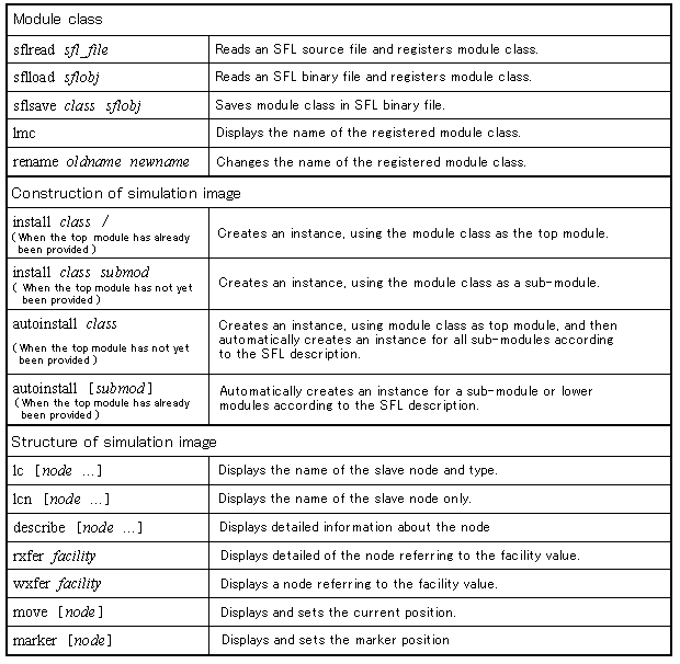
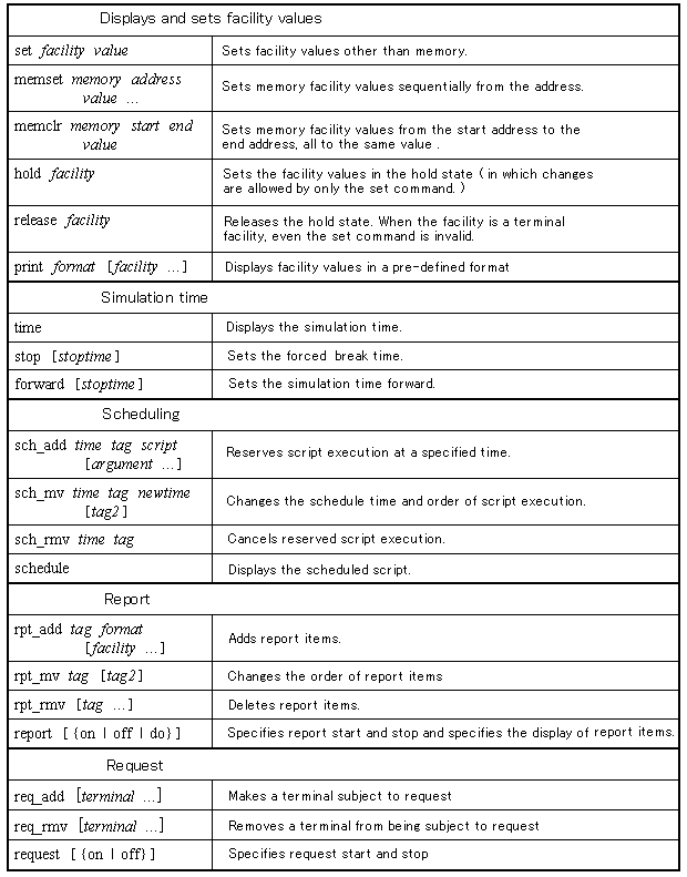
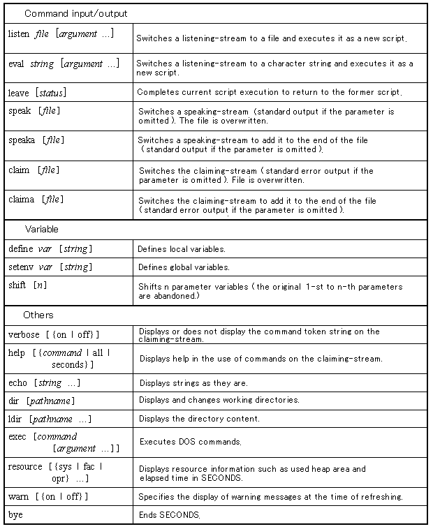
Table 5.2 gives a list of SECONDS commands.
<Table 5.2> A list of SECONDS commands
Bit string parameters
Integer parameters
Format
Specifying time by random number
SECONDS allows binary, octal, decimal and hexadecimal notations and their combinations as bit parameters:
	Bit string constant  	::= bit substring  {bit substring  }

	Bit substring 	::= binary notation  | octal notation  | decimal notation  | hexadecimal notation

	Binary notation 	::= B[bit width%]binary number{binary number}

	Octal notation 	::= O[bit width%]octal number{octal number}

	Decimal notation	::= D[bit width%]decimal number{decimal number}

	Hexadecimal notation 	::= X[bit width%]hexadecimal number{hexadecimal number}

	Binary number 	::= 0 | 1 | u | ?

	Octal number 	::= 0 | 1 | 2 | 3 | 4 | 5 | 6 | 7 | u | ?

	Decimal number 	::= 0 | 1 | 2 | 3 | 4 | 5 | 6 | 7 | 8 | 9

	Hexadecimal number 	::= 0 | 1 | 2 | 3 | 4 | 5 | 6 | 7 | 8 | 9

			  | a | b | c | d | e | f | u | ?

	Bit width 	::= integer
If the first bit substring of a bit string constant is given in binary notation, 'B' at the head can be omitted. If the bit width is omitted it is assumed to be the number of characters multiplied by 1, 3 and 4 respectively for binary, octal and hexadecimal notations. In decimal notation, the bit width is assumed to be 32 bits.
If the bit width is specified, and is different from the default bit width, one of the following occurs. If the specified bit width is greater than the default, '0' is added to the high-order bits (left side). If the specified bit width is smaller, then high-order bits are discarded.
If the bit width is specified in binary, octal or hexadecimal notation, '*' can be appended to the number only once. This denotes an appropriate number of repetitions (including no repetition) of the preceding number. The number of repetitions is determined such that the bit width remaining after subtracting the bit width assumed from the preceding or subsequent numbers in binary, octal or hexadecimal notation from the specified bit width is filled (starting from the lowest bit).
The number in a value parameter for set, memset and memclr commands can be '?' (if in binary, octal or hexadecimal notation). This denotes that the bit value is not to be changed. Any character other than 'B', 'O', 'D', 'X' and '%' can be inserted into a string as notation to delimit the string. These characters are all ignored.
An example of a bit string constant for a set command is given below (all the following set commands are equal):
	set reg "3%1*0 X5%-b X?** O6%455"

	set reg "3%1*0 X5%b X? O6%455"

	set reg "B110 B01011 B???? B101101"
Execution of this command changes the reg value to the following.
reg: uuu uuuuu uuuu uuuuuu -> 110 01011 uuuu 101101
SECONDS allows binary, octal, decimal and hexadecimal notations for integer parameters. Start with one of radices 'B', 'O', 'D' and 'X' and then follow it with a number in the respective notation (if radices are omitted, decimal notation is assumed).
In the forward, stop, and sch_add commands, adding '+' at the head of an integer for a stoptime or time parameter specifies a simulation time relative to the time when the respective command is issued.
The format parameter of the print and rpt_add commands is a character string. Except for "n" and "t", characters following "\" are output directly (that is literally, as they appear)output. "\n" and "\t" yield <newline> and <tab>, respectively. Alphanumerics following a "%" that does not follow "\" specify the facility value notation and are replaced with the character string shown below. Other characters are output literally, as they are appear.
The notation format specification is interpreted as a "%{digit}conversion character" pattern. Except when the conversion character is "t" or "T", the n-th conversion character in the format determines how the facility value specified by the n-th facility parameter is output. The digit string specifies the number of characters to be output as a result of conversion. If the number of characters is omitted, it is what is necessary to output the value.
The difference between uppercase and lowercase use in conversion characters is the difference in the way the value of a terminal facility not being driven is displayed. When an uppercase character is specified, 'z' is displayed. When a lowercase character is specified, no such value is displayed.
	<Conversion character>	  <Output>

	 b or B	      : Displays binary facility values

	 o or O	      : Displays octal facility values

	 d or D	      : Displays decimal facility values

	 x or X	      : Displays hexadecimal facility values

	 s or S	      : Displays state name of stage or segment facility

	 t or T	      : Displays the present time in decimal
If at least 1 bit out of 3 or 4 bits given in octal or hexadecimal notation is "u" or "z", "u" or "z" is displayed at the applicable position. If at least 1 bit in a facility value in decimal notation is "u" or "z", only 'u' or 'z' is displayed.
To use the print and rpt_add commands to output the value of a specific address word in a memory facility, specify "@address" following the facility name. The address is given as an integer.
In addition to being able to specify absolute or relative time in its time parameter, the sch_add command can scatter schedule times using random numbers.
The following three types of random numbers can be specified.
o  Random numbers following a uniform distribution
o  Random numbers following an exponential distribution
o  Random numbers following a normal distribution
Parameters are specified as follows. With random numbers, only relative time can be specified ('+' is not allowed).
%u min max
	Uniform distribution between min and max
%e min max mean
	Exponent distribution with the mean value of mean (only random numbers between min and maxare adopted)
%n min max mean variance
	Normal distribution with the mean value of min and the variance of variance (only random numbers between min and max are adopted)