 Back to the Contents of PARTHENON User's Manual
9. Reducer for Logic Inverters: RINV
9.1 Starting RINV
9.2 Example of Using RINV
RINV (Reducer for logic INVerters) accepts as input a netlist for a hierarchically structured circuit (in the NLD or PCD format), executes global optimization of polarity (reduces the number of inverters) for the whole circuit, and outputs a netlist for a hierarchically structured circuit as the result (in the NLD or PCD format).
-
rinv [-a] module_name directory ... [-r directory ...] -w directory
- module_name : top module name of the given circuit
- directory : Name of the directory in which NLD or PCD files are stored or in which the result is stored
- Selecting the '-a' option allows replacement of 'and', 'or', 'nand' and 'nor' with one another as appropriate. If it is not desirable to replace "nand" and "nor" with "and" and "or", as in the case of CMOS, don't specify this option.
- Following the top module name, specify the directories, one by one, where all NLD files and PCD files constituting the component elements of the module can be found. Generally, it is necessary to specify the directory where multiple NLD files forming a hierarchical structure are stored and the directory in the cell library where PCD files constituting primitive component elements are stored. The information on the logic cell names (nand--2, reg-1, etc.; see Section 4.3)" defined in PARTHENON is contained in the program, and hence PCD and NLD files of these names are not required. For example, the specification of a directory with only logic cells, e.g., %PARTHENON% \celldemo\start, can be omitted.
- The netlist (NLD file) in the directory specified after '-r' and all the component elements in it (whose classes may be in the directory specified before '-r') is not subject to optimization and the netlist output is the same as that input.
- The netlist after polarity optimization (the top module and all the NLD files constituting its component elements) are output to the directory specified after '-w.' Polarity optimization may remove inverters, replace logical gates with dual operations, and change the interface polarity between internal modules, but the hierarchical structure of the input netlist is retained as far as possible.
The following example shows an RINV execution of 'test.sfl' in 'a:\par\example.dir' in a manner similar to synthesis by 'auto.bat.' NLD/PCD files are input from test.2nd, a:\par\celldemo\start, and a:\par\celldemo\start_e (it is not always necessary to specify start and start_e in this example). Polarity optimization of the circuit with 'test' as the top module is executed, and the resulting netlist is stored in 'test.3rd.'
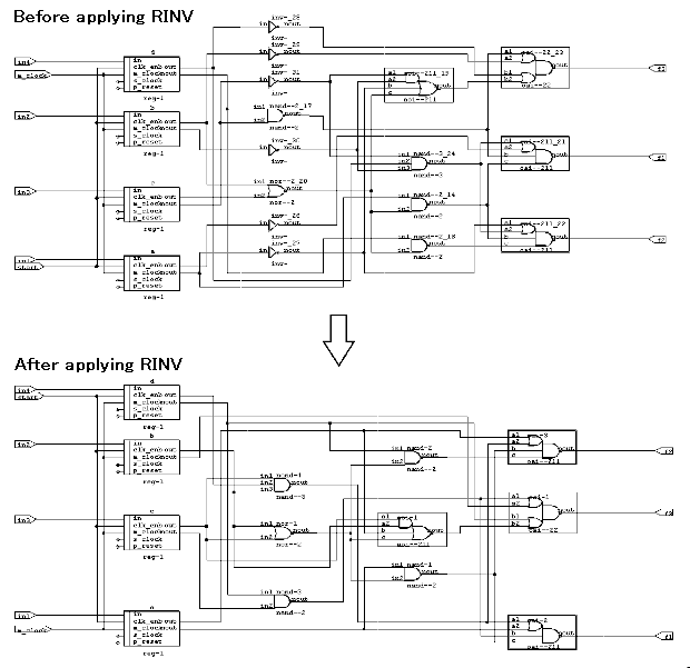
List 9.1 shows the execution example and Figure 9.1 shows the circuit before and after applying RINV.
<List 9.1> Message output example when RINV is started and executed
 1:  A>rinv test test.2nd a:\par\celldemo\start a:\par\celldemo\start_e -w test.3rd
 2:
 3:  ***************************************************************
 4:  * RINV  Version 2.3.0                              1994/07/05 *
 5:  * This program is a part of the PARTHENON system.             *
 6:  *                                 Copyright (C) 1989-1994 NTT *
 7:  ***************************************************************
 8:
 9:  Start to read NLD/PCD files
10:          Read test.2nd/test.nld
11:  Done
12:  There are 6 inverters
13:  Start inverter reduction
14:  Done
15:  There are 0 inverters
16:  Start to write NLD files
17:          Wrote test.3rd/test.nld
18:  Done
19:  Number of inverters
20:          6 ---> 0
21:
22:  A>
<Fig 9.1> Circuit example before and after applying RINV

