NLD_PS (NLD to PostScript) accepts a netlist for a hierarchically structured circuit (in the NLD/PCD format) as input, creates a logic circuit diagram, which is automatically divided into pages, and outputs it in a PostScript file.
You can print the logic circuit diagram by transferring this file to a PostScript printer. In addition, if a PostScript viewer, such as Ghostscript, is available, the circuit diagram can be displayed on the screen or printed on a non-PostScript printer.
Specifying (options)options
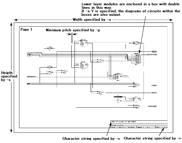
An arbitrary character string (up to 120 characters) specified in comment is inserted in a box in the lower right part of every page of the diagram. If this option is not specified, the relevant box is blank.
An arbitrary character string (up to 4 characters) specified in revision is inserted in a box in the lower right part of every page of the diagram. If this option is not specified, the relevant box is blank.
The minimum pitch of the diagram is set to value mm (0 < value < 4.0; the default value is 2.0 mm).
A4, B4 or height and width (unit: mm) specifies the page size of the diagram (210.0 < height < 9999.9, 148.0 < width < 9999.9; the default is A4; i.e., "210.0 x 297.0").
Selecting Y outputs the diagrams of the circuits within all sub-modules in the specified top module. Selecting N outputs no diagrams of circuits within sub-modules (the default is N).
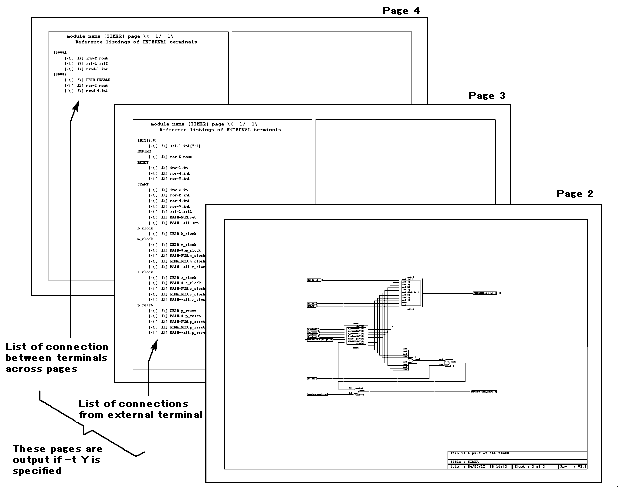
Selecting Y creates a list of connections from external terminals and a list of connections between terminals across different pages (excluding connections between only two terminals because they are indicated in the diagram), and adds them to the PostScript file (the default is N).
This specifies the PostScript file name to be created. If this is not specified, the standard output (i.e. the visual display) is selected.
The following example is the case of creating a circuit diagram of top module name TIMER from the NLD and PCD files in TIMER.1st and a:\par\celldemo\start, which appeared in the synthesis example in Section 2.3. As options, comments "This is a part of the TIMER" and revision "V2.3" are specified, and the creation of a list of connections is also specified. The resulting PostScript file is TIMER1.ps.
An execution example is shown in List 10.1. Figure 10.1 shows an example printout of TIMER1.ps.
<List 10.1> Examples of messages output when starting and executing NLD_PS
 1:  A>nld_ps  -c "This is a part of the TIMER" -r "V2.3" -t Y -o TIMER1.ps TIMER
     TIMER.1st a:\par\celldemo\start
 2:
 3:  ***************************************************************
 4:  * NLD_PS  Version 2.3.0                            1994/07/05 *
 5:  * This program is a part of the PARTHENON system.             *
 6:  *                                  Copyright(C) 1989-1994 NTT *
 7:  ***************************************************************
 8:
 9:  Read netlist.
10:        Reading [TIMER.1st/TIMER.NLD].
11:        Reading [TIMER.1st/SL8-2.NLD].
12:        Reading [a:\par\celldemo\start/INV-.PCD].
13:        Reading [a:\par\celldemo\start/NAND--3.PCD].
14:        Reading [a:\par\celldemo\start/NOR--4.PCD].
15:        Reading [TIMER.1st/DECR8.NLD].
16:        Reading [TIMER.1st/REG-8.NLD].
17:        Reading [a:\par\celldemo\start/NOR--8.PCD].
18:        Reading [a:\par\celldemo\start/NAND--2.PCD].
19:        Reading [a:\par\celldemo\start/REG---1.PCD].
20:        Reading [a:\par\celldemo\start/LOW-.PCD].
21:        Reading [a:\par\celldemo\start/NOR--2.PCD].
22:        Reading [TIMER.1st/SL1-2.NLD].
23:        Reading [a:\par\celldemo\start/REG--1.PCD].
24:        Reading [a:\par\celldemo\start/HIGH-.PCD].
25:  Schematics generation : from netlist to PostScript.
26:  Composing drawing data...
27:  module << TIMER >> .
28:        ...Split into 2 page(s).
29:        ...Component located.
30:        ...Nets routed.
31:        ...PostScript data made.
32:        ...Circuit diagram : 2 page(s).
33:        ...External pin list : 1 page(s).
34:        ...Internal port list : 1 page(s).
35:  finished.
36:
37:  A>
<Fig. 10.1> Example of diagram printout (the actual printouts are in A4 size)

